


 当前位置:
当前位置:Rev Up Your Fan Speed Control
[09-13 17:04:38] 来源:http://www.88dzw.com 控制技术 阅读:8723次
文章摘要:Abstract: Controlling the speed of a brushless DC cooling fan is discussed. Examples of discrete and IC fan speed controllers are shown. 12V, 24V and 48V designs are included, as well as isolated versions. Tachometer feedback for speed control is discussed. Speed control of the brushless DC fans com
Rev Up Your Fan Speed Control,标签:计算机控制技术,工厂电气控制技术,http://www.88dzw.comAbstract: Controlling the speed of a brushless DC cooling fan is discussed. Examples of discrete and IC fan speed controllers are shown. 12V, 24V and 48V designs are included, as well as isolated versions. Tachometer feedback for speed control is discussed.
Speed control of the brushless DC fans commonly used in PCs and other types of electronic equipment is complicated by their nonlinear behavior. As Figure 1 shows, the motors do not run at all until the voltage reaches a highly variable startup voltage and the speed is only approximately linear beyond that point.
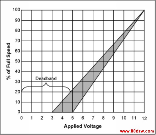
Figure 1. This graph shows the voltage vs. speed for a typical brushless DC fan. The fan turning starts somewhere between 3 to 5 volts. Predicting the exact starting voltage is difficult. The exact point varies from fan-to-fan, over the fan's operating life, and as a function of ambient conditions. Although the graph is linear above the starting point, most fans only approximate a linear relationship of voltage to speed. Closed loop fan speed regulation overcomes all of these difficulties.
Circuits which regulate fan speed can overcome these difficulties. The availability of motors with tachometer outputs facilitates the design of these circuits.
The Basic Fan Control Amplifier
For some time now there have been integrated circuits available that include a DAC (digital-to-analog converter) for controlling fan speed. These include PC system Health Monitors and dedicated fan control ICs, such as the MAX1669, with either a linear DAC output as well as PWM output. Although primarily designed for use in PCs, these ICs have found use in other types of electronic equipment. They are equipped with I²C or SMBus interfaces for communication with the controller, processor, or computer. Typically the DAC outputs are fed into either of two types of analog amplifier circuits to step up their voltage output for application to a fan.These systems are "open loop" and subject to start-up voltage requirements. A common approach is to feed full voltage to the fan for a short interval before lowering it to acheive the desired speed. The lowest feasible speed is determined empirically and because it varies with time and conditions, it requires constant re-verification.
Figure 2 depicts a schematic for a simple DAC-based "open loop" fan control. It is subject to the start-up limitations. While often used with fans equipped with tachometer outputs, the ICs only use these tachometer signals to monitor fan speed and determine if speed falls below "watchdog" limits. Because these tachometer signals are so prevalent, the opportunity readily exists to close the loop on fan control.
Tag:控制技术,计算机控制技术,工厂电气控制技术,控制技术
《Rev Up Your Fan Speed Control》相关文章
- › Rev Up Your Fan Speed Control
- › Reverse Compatibility of the D
- › YAMAHAREV100效果器使用说明
- › 奥地利微电子推出获得FlexRay V2.1 Rev B认证
- 在百度中搜索相关文章:Rev Up Your Fan Speed Control
- 在谷歌中搜索相关文章:Rev Up Your Fan Speed Control
- 在soso中搜索相关文章:Rev Up Your Fan Speed Control
- 在搜狗中搜索相关文章:Rev Up Your Fan Speed Control
分类导航
最新更新