


 当前位置:
当前位置:Rev Up Your Fan Speed Control
[09-13 17:04:38] 来源:http://www.88dzw.com 控制技术 阅读:8723次
文章摘要:Figure 7 shows a circuit for connecting MAX6650/MAX6651 to higher voltage fans. R1 is selected to be large enough to avoid loading the pull-up resistor, RPULLUP. R1 and R2 are set for an attenuation factor proportional to the increase in voltage above 12 volts. For example, in Figure 7, R1 and R2 at
Rev Up Your Fan Speed Control,标签:计算机控制技术,工厂电气控制技术,http://www.88dzw.comFigure 7 shows a circuit for connecting MAX6650/MAX6651 to higher voltage fans. R1 is selected to be large enough to avoid loading the pull-up resistor, RPULLUP. R1 and R2 are set for an attenuation factor proportional to the increase in voltage above 12 volts. For example, in Figure 7, R1 and R2 attenuate the tach signal to one-fourth of the value at the fan, since the fan operates at 48 volts. Once the attenuation factor for R1 and R2 have been determined, select R3 and R4 to have a somewhat greater attenuation factor so that the feedback voltage is more negative than the tach signal at all times. In Figure 7, the feedback signal is one-fifth the value at the drain of Q1. The relationship between tach and feedback signal is depicted in the scope traces shown in Figure 8. This attenuation relationship is necessary since the tachometer threshold, which is referred to the FB pin, is approximately 1.25 volts above the FB pin.
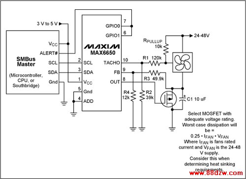
Figure 7. This circuit enables the MAX6650 to control a 48 volt fan by attenuating the feedback and tachometer signals to levels similar to what a 12 volt fan would produce.
 |
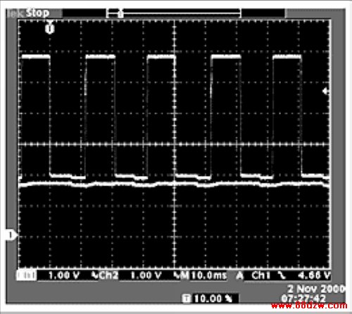 |
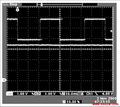
Figure 8. The scope photo on the left is taken at 780 rpm, driving a 48 volt motor. The right trace is taken at 1526 rpm. The square waveform is the tach signal at the TACHO pin of the MAX6650. The straight line is the feedback, taken at the FB pin of the MAX6650. Note that the voltage at the FB pin is more negative than the TACHO pin over the operating range of the fan. This is insured by setting the R3/R4 combination in Figure 7 for slightly more attenuation than the R1/R2 combination.
Tag:控制技术,计算机控制技术,工厂电气控制技术,控制技术
《Rev Up Your Fan Speed Control》相关文章
- › Rev Up Your Fan Speed Control
- › Reverse Compatibility of the D
- › YAMAHAREV100效果器使用说明
- › 奥地利微电子推出获得FlexRay V2.1 Rev B认证
- 在百度中搜索相关文章:Rev Up Your Fan Speed Control
- 在谷歌中搜索相关文章:Rev Up Your Fan Speed Control
- 在soso中搜索相关文章:Rev Up Your Fan Speed Control
- 在搜狗中搜索相关文章:Rev Up Your Fan Speed Control
分类导航
最新更新