


 当前位置:
当前位置:Rev Up Your Fan Speed Control
[09-13 17:04:38] 来源:http://www.88dzw.com 控制技术 阅读:8723次
文章摘要:Figure 2. Simple open-loop fan control is provided by some Health-Monitor, Super I/Os, and fan controllers typified by the MAX1669. This could be implemented with any DAC and any interface. The Health Monitor ICs have always had inputs for the tachometer, but only as a watchdog function, so the host
Rev Up Your Fan Speed Control,标签:计算机控制技术,工厂电气控制技术,http://www.88dzw.com
Figure 2. Simple open-loop fan control is provided by some Health-Monitor, Super I/Os, and fan controllers typified by the MAX1669. This could be implemented with any DAC and any interface. The Health Monitor ICs have always had inputs for the tachometer, but only as a watchdog function, so the host system can verify that the fan is running at minimum rate. The tach signal is not directly used in fan control. Because of start-up issues, some of the DAC range is thrown away resulting in a system that might actually have less than 7-bits of control over fan speed from an 8-bit DAC.
Closed Loop Fan Control Amplifier
An enhancement can be made to DAC drive fan controllers with the use of an external amplifier that closes the loop around the tachometer. This provides essentially linear control over the full range of 8-bit DAC codes from 0 to 255. Since the tachometer is already there, this only requires a little signal conditioning and a suitable amplifier arrangement. In the circuit shown in Figure 3, the tachometer pulses are conditioned such that all pulse width information is removed (differentiated) and only pulse rate information remains. These pulses representing frequency or fan speed are then used as the feedback to an integrating motor control amplifier.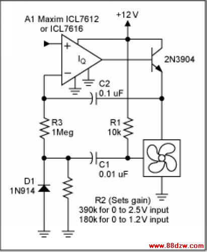
Figure 3. This closed loop fan control amplifier, for use with ICs such as those shown in Figure 2, uses the tachometer signals for feedback. This provides linear control over the full output range of the DAC. The fan will reliably start at any setting without the need to take the fan to full speed first.
The time constant of the differentiator is initially set to provide pulses just shorter than the duration of the shortest tach pulse at full fan speed. This usually provides too little gain. Gain can be increased by decreasing the value of either R2 or C1. Gain should be set such that the fan just achieves full speed with the full DAC output applied to the input of the amplifier circuit.
The time constant of the integrator is set to provide a smooth response to speed changes without any overshoot or hunting. Typically this is done empirically with the actual fan and system. The plots in Figure 4 and Figure 5 depict the response of the amplifier with the integration capacitor C2 at two values, 0.1µF and 1.0µF. Either value meets customary criteria for stability which dictates less than 25% overshoot.
Tag:控制技术,计算机控制技术,工厂电气控制技术,控制技术
《Rev Up Your Fan Speed Control》相关文章
- › Rev Up Your Fan Speed Control
- › Reverse Compatibility of the D
- › YAMAHAREV100效果器使用说明
- › 奥地利微电子推出获得FlexRay V2.1 Rev B认证
- 在百度中搜索相关文章:Rev Up Your Fan Speed Control
- 在谷歌中搜索相关文章:Rev Up Your Fan Speed Control
- 在soso中搜索相关文章:Rev Up Your Fan Speed Control
- 在搜狗中搜索相关文章:Rev Up Your Fan Speed Control
分类导航
最新更新