


 当前位置:
当前位置:双极性控制数字放大器-Dual-Polarity Ampli
[09-13 17:05:18] 来源:http://www.88dzw.com 控制技术 阅读:8403次
文章摘要:Abstract: This application note discusses using digital potentiometers for gain control in traditional operational amplifier (op amp) circuits. Examples are given for typical op amp configurations (inverting, non-inverting) where the digital pot is used as a replacement for standard mechanical poten
双极性控制数字放大器-Dual-Polarity Ampli,标签:计算机控制技术,工厂电气控制技术,http://www.88dzw.comAbstract: This application note discusses using digital potentiometers for gain control in traditional operational amplifier (op amp) circuits. Examples are given for typical op amp configurations (inverting, non-inverting) where the digital pot is used as a replacement for standard mechanical potentiometers.
This tech brief requires an understanding of configuring op amps in typical gain control circuits. Both linear and non-linear digital pot applications are discussed. A basic technical overview of the requirements needed to transition audio and other potentiometer/op amp applications from traditional mechanical potentiometers to solid-state potentiometers is given. Also provided is the background required for the implementation of digital potentiometers as a replacement for mechanical potentiometers in calibration and bias control used in applications such as industrial control, audio, and telecommunications.
|
|
Introduction
The circuit of Figure 1 provides a means of amplifying a signal either in an inverting or non-inverting mode. When switch S1 is off and S2 is on, the circuit behaves as a regular inverting amplifier. When S1 is on, and S2 is off, the signal is fed to the noninverting input of the op amp, and thus the circuit behaves as a noninverting amplifier. If S1 and S2 are monolithic analog switches, the control of this circuit may be accomplished with a digital signal.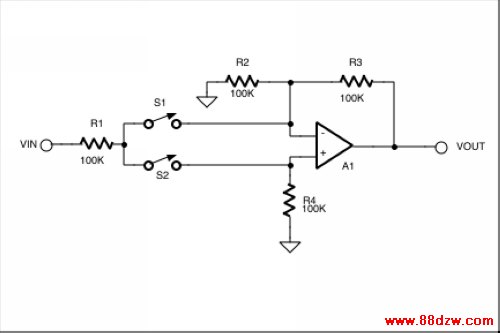
Figure 1. When S1 is open and S2 closed, this circuit is an inverting amplifier with a gain of -1. When S1 is closed and S2 opened, the circuit is a noninverting amplifier with a gain of +1.
Digital Pot Simplifies Circuit
Instead of using switches, a potentiometer may be used. When the wiper is at the high end of the pot, the noninverting mode is selected; when it's at the other end, the inverting mode is chosen. Using a linear digital potentiometer like the DS1267, as in Figure 2, gives digital control of not only the polarity but also the gain of the amplifier. Since many digital potentiometers come in dual configurations, this allows an "extra" pot in a circuit to be used to accomplish this signal processing task. The wiper value of the pot is written over the 3-wire interface consisting of /RST, CLK, and DQ. A wiper value of 00000000 will set the wiper to the low end of the pot, making this an inverting (gain = -1) circuit. A wiper value of 11111111 will set the wiper to the high end of the pot, placing the circuit in a noninverting (gain = +1) configuration. Wiper settings in between these values will result in a change in gain sweeping from +1 to -1.
Tag:控制技术,计算机控制技术,工厂电气控制技术,控制技术
《双极性控制数字放大器-Dual-Polarity Ampli》相关文章
- › 双极性控制数字放大器-Dual-Polarity Ampli
- 在百度中搜索相关文章:双极性控制数字放大器-Dual-Polarity Ampli
- 在谷歌中搜索相关文章:双极性控制数字放大器-Dual-Polarity Ampli
- 在soso中搜索相关文章:双极性控制数字放大器-Dual-Polarity Ampli
- 在搜狗中搜索相关文章:双极性控制数字放大器-Dual-Polarity Ampli
分类导航
最新更新