


 当前位置:
当前位置:Rev Up Your Fan Speed Control
[09-13 17:04:38] 来源:http://www.88dzw.com 控制技术 阅读:8723次
文章摘要:Figure 4. This plot depicts the closed-loop fan control amplifier with a 0.01µF integrating capacitor responding to a step change input.Figure 5. This plot depicts the closed-loop fan control amplifier with a 1µF integrating capacitor responding to a step change input.Integrated Solution
Rev Up Your Fan Speed Control,标签:计算机控制技术,工厂电气控制技术,http://www.88dzw.com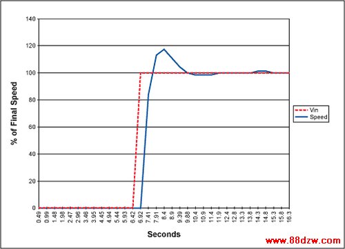
Figure 4. This plot depicts the closed-loop fan control amplifier with a 0.01µF integrating capacitor responding to a step change input.
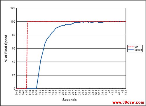
Figure 5. This plot depicts the closed-loop fan control amplifier with a 1µF integrating capacitor responding to a step change input.
Integrated Solutions to Fan Regulation
Fan speed regulation design is simplified greatly by using a dedicated IC such as the MAX6650 or MAX6651.The MAX6650 is designed to control a single fan. The MAX6651 controls a single fan and can monitor and watchdog three additional fan tachometer outputs. Multiple MAX6651s controlling multiple fans can be synchronized. These ICs are designed to interface to an I²C or SMBus, and use the tachometer feedback from fans to regulate their speed. The ICs include extensive programmability to accommodate a variety of fan speeds and types. Figure 6 depicts a typical connection for the MAX6650.
Note from the circuit of Figure 6 that the MAX6650/MAX6651 are designed to be used with an external pass transistor. Feedback is taken from the drain of the transistor to the terminal on the IC labeled "FB", since the output stage of the MAX6650/MAX6651 is an analog DAC and amplifier combination. This DAC/amplifier combination requires local feedback. The feedback of the complete loop is actually the tachometer signal of the fan, and this is also returned to the MAX6650/MAX6651. These devices will drive the fan until that tach signal matches the programmed period in the speed register in the MAX6650/MAX6651.

Figure 6. The MAX6650 shown here provides a complete integrated, interfaceable solution to fan speed regulation.
Controlling High Voltage Fans
Some fans are rated at up to 24 to 48 volts. The MAX6650/MAX6651 can easily be adapted to controlling these higher voltage fans by simply attenuating the feedback and tachometer signals by an amount proportional to the difference between the actual supply and 12 volts. In essence, the MAX6650/MAX6651 can be "tricked" into thinking it is controlling a 12 volt fan. This is accomplished with simple attenuation networks on both the feedback and tachometer outputs.When setting the values for these attenuators, the tachometer feedback signal at the TACHO pin should always be kept more positive than the voltage at the FB pin. This is done with a slightly greater attenuation on the FB network. The FB network can actually tolerate a wide range of attenuation since that only sets the local gain of the MAX6650/MAX6651 output stage. That output stage is still enclosed within the greater feedback loop formed by the TACHO signal.
Tag:控制技术,计算机控制技术,工厂电气控制技术,控制技术
《Rev Up Your Fan Speed Control》相关文章
- › Rev Up Your Fan Speed Control
- › Reverse Compatibility of the D
- › YAMAHAREV100效果器使用说明
- › 奥地利微电子推出获得FlexRay V2.1 Rev B认证
- 在百度中搜索相关文章:Rev Up Your Fan Speed Control
- 在谷歌中搜索相关文章:Rev Up Your Fan Speed Control
- 在soso中搜索相关文章:Rev Up Your Fan Speed Control
- 在搜狗中搜索相关文章:Rev Up Your Fan Speed Control
分类导航
最新更新