


 当前位置:
当前位置:Interfacing the DS1620 to the
[09-13 17:03:31] 来源:http://www.88dzw.com 控制技术 阅读:8716次
文章摘要:Abstract: Communication with the DS1620 digital temperature sensor IC is achieved via a simple 3-wire interface. There are a number of differences between this interface and the Motorola SPI™ interface. However, a few minor hardware and software modifications allow the DS1620 to be effectively
Interfacing the DS1620 to the,标签:计算机控制技术,工厂电气控制技术,http://www.88dzw.comAbstract: Communication with the DS1620 digital temperature sensor IC is achieved via a simple 3-wire interface. There are a number of differences between this interface and the Motorola SPI™ interface. However, a few minor hardware and software modifications allow the DS1620 to be effectively incorporated into an SPI based system.
This application note is a courtesy of Michel St-Hilaire and Marc Desjardins from XyryX Technologies, Quebec city, Province of Quebec, Canada.
Introduction
The DS1620 Digital Thermometer and Thermostat provides 9-bit temperature readings which indicate the temperature of the device. With three thermal alarm outputs, the DS1620 can also act as a thermostat. Temperature settings and temperature readings are all communicated to/from the DS1620 over a simple 3-wire interface.However, the SPI interface found on many Motorola processors cannot directly communicate with the 3-wire interface found on the DS1620. First, the data flow to and from the DS1620 is multiplexed on only one pin (DQ) while SPI needs two separate signals (MOSI, MISO).
Second, most SPI interfaces are limited to 8-bit data transfer, complicating sending and receiving the 9-bit temperature readings to and from the DS1620. In addition, the DS1620's interface transfers LSB first, while SPI is an MSB-first communication protocol.
Lastly, the RST-bar is unlike a CS-bar (chip select) signal in that RST-bar must be high from the beginning of a transfer (protocol) to the end of all transfer of data (e.g. 9th bit transferred when reading temperature value).
Despite all these constraints, a fairly simple solution can be found which allows an SPI interface to communicate with a DS1620. This technique is described in this application note.
SPI Interface
The circuit shown in Figure 1 can be used to control data flow direction with an SPI bus interfaced to a DS1620. This circuit could be integrated into a small PAL if desired.The purpose of the DIR signal is to select between sending data to or receiving data from the DS1620. When DIR is low, the DS1620 is receiving data; if DIR is high, data is being read by the SPI controller.
The resistor is necessary to prevent contention between the output of the tri-state buffer on the MOSI line and the DQ pin of the DS1620, because after a READ command protocol has been received by the DS1620, its DQ pin changes direction from input to output in a few hundred nanoseconds. This time is much too short for the microprocessor controlling the DIR signal to take action.
When connecting multiple peripherals on the same SPI bus, the MISO signal must be tri-stated when the DS1620 is not accessed to prevent contention with the MISO signal of other peripherals. That is why the RST-bar signal is necessary in the logic which determines the data direction.
Note that the SPI clock is wired directly to the CLK pin of the DS1620. The software has to take care of the polarity and phase of the SPI clock to be compatible with the CLK timing requirements of the DS1620.
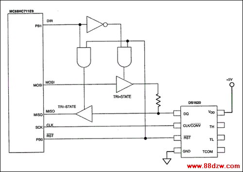
Figure 1. SPI to DS1620 interface circuit.
Tag:控制技术,计算机控制技术,工厂电气控制技术,控制技术
《Interfacing the DS1620 to the》相关文章
- › ATX开关稳压电源与CRT显示器电路图集000068-INTEL MODEL NO FM370...
- › Interfacing the DS1620 to the
- › Intersil智能传感器解决方案
- › Intersil 推出光传感器
- › Intersil 推出双输出降压控制器
- › 基于AVR单片机的多任务嵌入式Internet系统设计
- 在百度中搜索相关文章:Interfacing the DS1620 to the
- 在谷歌中搜索相关文章:Interfacing the DS1620 to the
- 在soso中搜索相关文章:Interfacing the DS1620 to the
- 在搜狗中搜索相关文章:Interfacing the DS1620 to the
分类导航
最新更新