


 当前位置:
当前位置:Keep Power Consumption in Chec
[11-20 17:32:32] 来源:http://www.88dzw.com 模拟电子技术 阅读:8997次
文章摘要:Figure 1. An automatic jack-detection circuit.Headset DetectionThe audio socket in Figure 1 is designed to handle the popular three-conductor audio plug. This plug connects either to a stereo headphone or a mono headset with microphone. You can easily differentiate between the stereo and mono-plus-m
Keep Power Consumption in Chec,标签:模拟电子技术基础,模拟电子电路,http://www.88dzw.com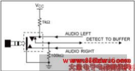
Figure 1. An automatic jack-detection circuit.
Headset Detection
The audio socket in Figure 1 is designed to handle the popular three-conductor audio plug. This plug connects either to a stereo headphone or a mono headset with microphone. You can easily differentiate between the stereo and mono-plus-microphone headset by using the circuits discussed below. These circuits leverage the fact that headphone resistance is low (usually 8Ω, 16Ω, or 32Ω) and that microphone resistance is high (600Ω to 10kΩ).
A brief introduction to the common audio jack and the electret microphone is helpful in understanding these circuits. In a three-conductor audio jack (Figure 2), the "tip" carries the left-channel audio for a stereo headphone or the microphone connection for a mono headset with microphone. For stereo headphones, "ring" connects to the right channel and "sleeve" to ground. For a mono headset with microphone, ring connects to the input audio channel for the mono microphone and sleeve connects to ground.
Figure 2. A three-conductor audio jack.
Electret Microphones
A typical electret microphone (Figure 3) has a condenser element whose capacitance varies in response to mechanical vibrations, thereby providing voltage variations proportional to the sound waves. Electret microphones have a permanent, built-in static charge and, therefore, require no external power source. They do, however, require a few volts to power an internal preamplifier FET.
Figure 3. An electrical model of an electret microphone.
The electret microphone appears as a constant-current sink that provides very high output impedance. Its high impedance is then converted by the FET preamplifier to the low impedance necessary for interfacing with the subsequent amplifier. Thus, the electret microphone's low cost, small size, and good sensitivity make it a good choice for applications like hands-free cell-phone headsets and computer sound cards.
The microphone is biased through a resistor (usually 1kΩ to 10kΩ) and a supply voltage that provides the necessary constant-bias current. This bias current ranges from 100µA to about 800µA, depending on the particular microphone and its manufacturer. The bias resistor is selected according to the applied supply voltage, the desired bias current, and the required sensitivity. Based on these factors, the necessary bias voltage varies from part to part and with operating conditions. A 2.2kΩ load resistor with 3V supply drawing 100µA, for example, develops a bias voltage of 2.78V. A similar resistor drawing 800µA under similar conditions develops a bias voltage of 1.24V.
- 上一篇:音频DAC的工作原理
《Keep Power Consumption in Chec》相关文章
- › Keep Power Consumption in Chec
- 在百度中搜索相关文章:Keep Power Consumption in Chec
- 在谷歌中搜索相关文章:Keep Power Consumption in Chec
- 在soso中搜索相关文章:Keep Power Consumption in Chec
- 在搜狗中搜索相关文章:Keep Power Consumption in Chec