


 当前位置:
当前位置:自动测试设备的预算-Automatic Test Equip
[09-13 17:05:13] 来源:http://www.88dzw.com 控制技术 阅读:8238次
文章摘要:Connecting a PC to Test EquipmentThe PC Parallel PortOne of the easiest ways to connect test equipment and the device under test (DUT) to a personal computer is through the use of the PC's parallel port. This port is standard equipment on nearly every IBM-compatible PC. The standard parallel por
自动测试设备的预算-Automatic Test Equip,标签:计算机控制技术,工厂电气控制技术,http://www.88dzw.comConnecting a PC to Test Equipment
The PC Parallel Port
One of the easiest ways to connect test equipment and the device under test (DUT) to a personal computer is through the use of the PC's parallel port. This port is standard equipment on nearly every IBM-compatible PC. The standard parallel port provides 12 logic outputs and five inputs, which can be connected directly to TTL/CMOS circuits. You can also use an enhanced version of the parallel port found on many modern computers. Software design is simple: The PC parallel port is easy to program using C or Basic. For programming details, refer to Parallel Port Complete by Jan Axelson.Because PCs contain the hardware needed to operate the PC parallel port, there is no need to open the PC to install a card. Using the parallel port thereby eliminates the risk of ESD damage due to improper handling procedures while the computer is open.
Engineers connect the parallel port to various types of interfaces. The parallel port often drives 2-wire I²C interfaces. Because the I²C standard specifies that I²C transmitters provide logic signals via open-collector outputs, the interface circuitry can be as simple as a single 74HC05 open-collector inverter IC. Figure 2 illustrates a parallel-port-to-I²C interface that transmits and receives data to and from a DUT.
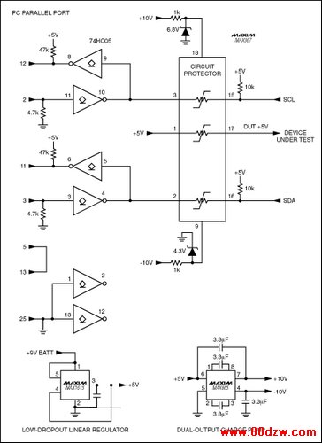
Figure 2. This parallel-port-to-I²C interface provides the open-collector connection to the I²C serial port mandated by the I²C specification. The MAX367 circuit-protector IC keeps voltages that exceed the supply rails from damaging the interface circuitry as well as the parallel port itself.
Along with the advantages of communicating via the PC parallel port, a number of minor pitfalls accompany its use. For example, when using programs written for Microsoft Windows, the number of unused parallel-port input pins you can dedicate to the application is reduced to four. This problem occurs because programs written for Microsoft Windows cannot reliably determine the address of the parallel port. Connecting one of the output pins of the parallel port to one of its input pins allows software to automatically determine the parallel-port address. Doing so, however, reduces the number of usable input pins to four. A more difficult problem can occur if voltages that exceed the supply rails come in contact with any of the circuitry connected to the parallel port; these voltages can destroy the circuitry external to the computer as well as the parallel port itself.
A way to guard against excessive voltage is to include a circuit protector chip. The MAX367 circuit-protector IC pictured in Figure 2 protects against such occurrences. (The circuit shown in this figure is available on an interface board from Maxim.) When voltage applied to either side of any protector within this IC exceeds the supply rails, the resistance of the specific protector becomes very high, preventing appreciable current from flowing through it. Also, the chip limits the voltage to within the supply rails, ensuring that any high voltages inadvertently placed on the SCL, SDA, or DUT +5V pins are prevented from damaging the interface circuitry as well as the parallel port.
上一页 [1] [2] [3] [4] [5] [6] [7] [8] [9] 下一页
Tag:控制技术,计算机控制技术,工厂电气控制技术,控制技术
- 上一篇:场效应管的识别方法及好坏判断
《自动测试设备的预算-Automatic Test Equip》相关文章
- › 自动测试设备的预算-Automatic Test Equip
- › 基于多MCU的自动测试诊断系统的设计
- › 基于单片机控制的热源自动测试仪
- › 自动测试软件可靠性量化评估技术研究
- 在百度中搜索相关文章:自动测试设备的预算-Automatic Test Equip
- 在谷歌中搜索相关文章:自动测试设备的预算-Automatic Test Equip
- 在soso中搜索相关文章:自动测试设备的预算-Automatic Test Equip
- 在搜狗中搜索相关文章:自动测试设备的预算-Automatic Test Equip
分类导航
最新更新