


 当前位置:
当前位置:Automatic Test Equipment on a
[09-13 17:03:19] 来源:http://www.88dzw.com 控制技术 阅读:8688次
文章摘要:Another important precaution is to make sure to identify high-impedance nodes, such as those found at op-amp inputs. Because these nodes are sensitive to noise, keep them away from noisy signal lines. Noisy lines are those that carry fast rise- and fall-time signals, and they are often fed from digi
Automatic Test Equipment on a,标签:计算机控制技术,工厂电气控制技术,http://www.88dzw.comAnother important precaution is to make sure to identify high-impedance nodes, such as those found at op-amp inputs. Because these nodes are sensitive to noise, keep them away from noisy signal lines. Noisy lines are those that carry fast rise- and fall-time signals, and they are often fed from digital or video sources.
Such high-speed signals may need to be routed through a transmission line, depending on the distance over which they travel. Use special controlled-impedance layout techniques to incorporate these transmission lines in the printed-circuit board. These lines require precisely calculated dimensions and are typically routed without vias.
When testing numerous devices simultaneously, make sure that one failed device doesn't prevent the testing of the remaining devices. This problem can occur when a device under test's power-supply lead is shorted to ground; this short can sufficiently load the power supply to prevent accurate testing of the remaining devices. Ballast resistors connected in series with the power-supply lead of each device under test keep this problem from occurring.
When gang-testing a large number of devices, it's best to use hardware that operates independently of software to identify and quickly disconnect any short-circuited DUTs, thus preventing further damage. The added delay that software can contribute could increase the damage incurred by excessive current. Also, if this excessive current loads the supply that powers the microprocessor, the actions ordered by the software might not happen. Figure 6 shows an example of this type of hardware; this circuit illustrates how the tester (Figure 5) detects overcurrent faults. When requested by the control software, this circuit's power-up flip-flop is set, which switches on the power MOSFET Q2. The MAX472 current-sensing device senses the supply current drawn through the 0.5-ohm resistor (R4) and into the DUT. If the current through R4 exceeds 160mA, the voltage across resistor R11 activates one of U2's two comparators. If this overcurrent condition persists for more than approximately 30 milliseconds, C1 charges sufficiently to trip U2's second comparator, which sets the overcurrent flip-flop. This condition disables Q2 immediately. The control software detects the overcurrent alarm and identifies the failed device, while the testing of the other devices continues. The control software must remove and then reassert the power-up signal before Q2 can again power on.
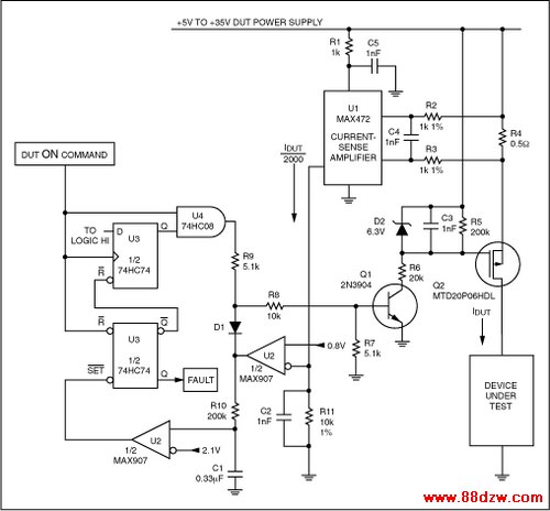
Figure 6. This circuit detects excessive current flow into the device under test, subsequently removes power from the device, and identifies the failed device to the tester's microprocessor via the fault signal.
Prior to laying out the board, it's helpful to prototype the various sections of circuitry and test them manually. Doing this ensures that these circuits function properly prior to placing them together with additional circuits on a single board and under the control of the IEEE-488 bus.
上一页 [1] [2] [3] [4] [5] [6] [7] [8] [9] 下一页
Tag:控制技术,计算机控制技术,工厂电气控制技术,控制技术
- 上一篇:高压变频器的选型注意事项
《Automatic Test Equipment on a》相关文章
- › 自动测试设备的预算-Automatic Test Equip
- › 自动重试控制器套装电信应用-Auto-Retry Contr
- › Automatic Test Equipment on a
- › Automatically Initializing Data Segment Values in MAX-IDE
- › 基于AutoCAD的线切割加工CAD/CAM技术
- 在百度中搜索相关文章:Automatic Test Equipment on a
- 在谷歌中搜索相关文章:Automatic Test Equipment on a
- 在soso中搜索相关文章:Automatic Test Equipment on a
- 在搜狗中搜索相关文章:Automatic Test Equipment on a
分类导航
最新更新