


 当前位置:
当前位置:CPLD设计的数码管驱动显示电路
[09-12 18:34:30] 来源:http://www.88dzw.com EDA/PLD 阅读:8650次
文章摘要:图 1.8 七段译码器模块DISPlibrary ieee;use ieee.std_logic_1164.all;entity disp isport(d:in std_logic_vector(3 downto 0);q:out std_logic_vector(6 downto 0));end disp;architecture rtl of disp isbeginprocess(d)begincase d iswhen"0000"=>q<="0111111";when"0001"=>q<="
CPLD设计的数码管驱动显示电路,标签:eda技术,eda技术实用教程,http://www.88dzw.com
图 1.8 七段译码器模块DISP
library ieee;
use ieee.std_logic_1164.all;
entity disp is
port(d:in std_logic_vector(3 downto 0);
q:out std_logic_vector(6 downto 0));
end disp;
architecture rtl of disp is
begin
process(d)
begin
case d is
when"0000"=>q<="0111111";
when"0001"=>q<="0000110";
when"0010"=>q<="1011011";
when"0011"=>q<="1001111";
when"0100"=>q<="1100110";
when"0101"=>q<="1101101";
when"0110"=>q<="1111101";
when"0111"=>q<="0100111";
when"1000"=>q<="1111111";
when thers=>q<="1101111";
end case;
end process;
end rtl;
1.3.5 驱动八位数码管显示的整体电路
将各个模块连接起来构成整体电路图如图 1.9 所示,可以实现用CPLD 设计一个驱动八位数码管显示电路的功能。clk 是时钟脉冲输入信号,经过时钟脉冲计数器CN8 模块,将信号以3 位2 进制数的形式输出,输出信号是COUT[2..0]。时钟脉冲计数器CN8 的输出同时作为3 线―8 线译码器DECODER3_8 和八选一数据选择器SEL81 地址码SEL[2..0]的输入。时钟脉冲计数器CN8 的输出经过3 线―8 线译码器DECODER3_8 译码其输出信号Vss[7..0]接到八位数码管的阴极Vss7、Vss6、Vss5、Vss4、Vss3、Vss2、Vss1、Vss0 端,决定点亮哪位数码管。同时时钟脉冲计数器CN8 模块输出的信号也进入数据选择器SEL81 地址码SEL[2..0]的输入,进行输出数据的选择,其输出是Q[3..0]。八选一数据选择器SEL81 模块的输出是Q[3..0]再经过七段译码器DISP 模块,将其翻译成可以用数码显示管的数据。七段译码器DISP 模块的输出Q[6..0]分别经300 欧电阻接数码显示管的a~g 管脚。八选一数据选择器模块的输入端,可根据具体需要进行设计。
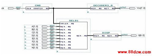
图 1.9 驱动八位数码管显示的整体电路
《CPLD设计的数码管驱动显示电路》相关文章
- › CPLD应用电路图
- › CPLD模块电路图
- › 基于AVR和CPLD的高速数据采集系统
- › 一种基于CPLD的声发射信号传输系统设计
- › 基于CPLD的臭氧电源控制系统的软硬件设计
- › 基于CPLD/FPGA的CMI编码设计与实现
- 在百度中搜索相关文章:CPLD设计的数码管驱动显示电路
- 在谷歌中搜索相关文章:CPLD设计的数码管驱动显示电路
- 在soso中搜索相关文章:CPLD设计的数码管驱动显示电路
- 在搜狗中搜索相关文章:CPLD设计的数码管驱动显示电路