


 当前位置:
当前位置:自己动手制造at89c51编程器 (英文)
[10-10 20:38:44] 来源:http://www.88dzw.com 微机|单片机 阅读:8170次
文章摘要:Figure 2 shows the circuit diagram of the interface adapter card required for the programming of 20 pin Flash devices. Figure 2: Interface Adapter circuit diagram V3.0sConstructing the BoardThe prototype board may be built using universal PCB with point-to-point wiring. If you want to make your ow
自己动手制造at89c51编程器 (英文),标签:电路设计,http://www.88dzw.comFigure 2 shows the circuit diagram of the interface adapter card required for the programming of 20 pin Flash devices.
Figure 2: Interface Adapter circuit diagram V3.0s
Constructing the Board
The prototype board may be built using universal PCB with point-to-point wiring. If you want to make your own PCB, download the PcbsPgm89v3.zip file which contains the printer files for the HP laser printer or download the PcbsPCX.zip file which contains PCX graphics format pcb files. Figure 3 shows the components layout of the programmer pcb.For printing the PRN files on laser printer run the following command, this will print the all pcb files.
COPY *.PRN PRN/B
For the bill of material of the project view the file Pgm89v3PartsList.txt
The schematics and the pcbs of the project were designed using OrCAD softwar
Figure 3: Components layout of the Programmer PCB V3.0
Software
Pgm89v3.zip file is used to run the programmer. This is a Windows program which can be used under
Windows 95 & 98. The main screen of the program is shown in figure 4.Following are the main features of this software,
- Read and Write the Intel Hex File
- Read Chip info
- Clear, Fill & Edit Program Buffer
- Verify with Program Buffer
- Reload current Hex File
- Display Data Checksum
- Program selected Lock Bits & ISP fuse
- Parallel Port Selection LPT1, 2 & 3
Windows NT/2000/XPTo use the software with the above operating systems, an i/o port driver is required. There are many freeware
i/o port drivers are available on the web, the following port driver can be used with the Pgm89 programmer,http://www.beyondlogic.org/porttalk/porttalk.htm
Study the web page and the readme file included in the port driver zip file for further information.
The programmer software uses the following i/o port addresses,Lpt1 Port @ 378H
Lpt2 Port @ 278H
Lpt3 Port @ 3BCHI/O Port @ 61H
I/O Port @ 42H & 43H
Note:
In order to insure safe insertion & removal of the u-controller from programmer ZIF socket make sure programmer power supply is turned on before starting the program and the red LED D1 must be turned off when the program is started. The u-controller should be placed or removed from the ZIF socket when the red LED D1 is off.
Also note that the software does not provide the erase command because this function is performed automatically during device programming. If you are required to erase the controller first use the clear buffer command in edit menu then program the controller, this will erase the controller memory.
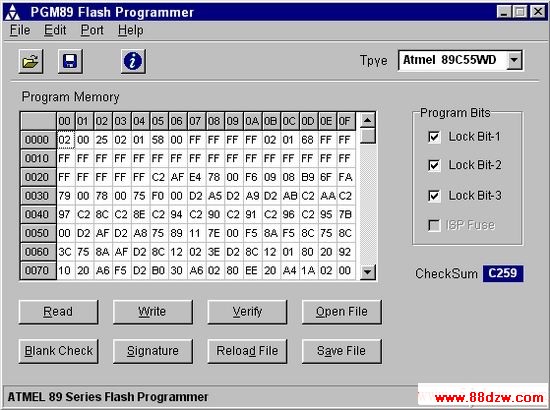
Figure 4: Main screen of the program PGM89v3
- 上一篇:自制51芯片仿真器完全手册
《自己动手制造at89c51编程器 (英文)》相关文章
- › 自己动手搞定笔记本电脑无法充电
- › 死而复生---自己动手修显卡
- › 自己动手彻底解决鼠标关机后仍然发光的问题
- › 死而复生-自己动手修显卡
- › 自己动手维护鼠标和键盘
- › 自己动手修理键盘
- 在百度中搜索相关文章:自己动手制造at89c51编程器 (英文)
- 在谷歌中搜索相关文章:自己动手制造at89c51编程器 (英文)
- 在soso中搜索相关文章:自己动手制造at89c51编程器 (英文)
- 在搜狗中搜索相关文章:自己动手制造at89c51编程器 (英文)